About Me

Wednesday, 29 May 2019

How catalysts in AHUs can improve indoor air quality

How catalysts in AHUs can improve indoor air quality

Electrostatic precipitators can stop PM2.5 dust particles from entering buildings, but could create dangerous levels of ozone. Catalysts in AHUs may be the answer, says Staffordshire University’s Derek Wardle
Credit: iStock.com/8213erika
Fine dust particles of diameters 2.5 microns (designated PM2.5) and less have harmful effects on people’s respiratory systems when inhaled. Ultrafine particles of 0.1 microns can pass into the blood system, which carries them to the heart and around the body. Particles also become permanently embedded in the lungs, reducing their capacity and making it more difficult to breathe. Analyses have shown traces of heavy metals and organic carcinogens form part of the total distribution of these particulates.
According to a 2013 report, Clean Air London, the quality of air in urban areas can be worse inside buildings than outside. The most common forms of pollution at and above molecular level are fine and ultrafine particulate matter, for example ≤PM2.5, including particulates emitted from traffic exhausts, power stations and bio-aerosols. Without filtration, more than 50% of indoor air pollution comes from outside.
Figure1: Cross-section of the new ESP design, including a catalyst and ozone sensor
A study conducted by the EU air quality and emissions policy committee concluded: ‘As buildings become virtually “airtight” to improve energy efficiency, it becomes increasingly important to install efficient air-filtration devices as a minimum requirement and as part of their ventilation systems.’
An efficient and reliable method of preventing particulate matter from entering (and leaving) non-residential buildings must be sought. There are viable choices, such as fabric filtration, cyclonic separation and electrostatic precipitation. This article focuses on electrostatic precipitators (ESPs), which all operate in much the same way. Incoming PM receives an electrostatic charge, which causes it to migrate to one or more oppositely charged or grounded collecting surfaces. The PM builds up on the collecting surface, where it remains until removed by mechanical means, such as rapping, where vibrations imparted to the electrodes remove the collected particles. During removal, the ‘caked’ PM falls into storage hoppers, although a significant amount becomes re-entrained in the gas flow. In single-section ESPs, re-entrained particles are carried through to the atmosphere. To meet specified emission targets, some precipitators are built with two or more sections aligned in series. Each section reduces re-entrainment until the specification is met.
The layer of ozone surrounding the Earth in the stratosphere is beneficial to life because it absorbs harmful ultra-violet radiation emitted from the sun. Unfortunately, ozone is also found in the troposphere, from ground level upwards, where it is harmful to life above certain concentrations. Ozone is a powerful oxidant that reacts with the body’s internal tissues – even short-term exposure can cause shortness of breath and chest pain. According to Reiser et al and Witschi, long-term exposure can lead to severe respiratory discomfort and, possibly, lung cancer.

ESPs, operating at high voltages, produce ozone to unacceptable levels that must not be distributed throughout a building
Another property of ozone to be considered, especially in the built environment, is its half-life. The work of McClurkin et al indicates that, in closed environments, this is dependent on air circulation, temperature and humidity, and may be much longer (up to 24 hours) than indicated previously in published data (30-40 minutes). ESPs, operating at high voltages, produce ozone to unacceptable levels that must not be distributed throughout a building. Ozone generation occurs as a result of the coronal discharge at the electrodes during particle charging. As health, safety and environmental protection pressures grow, the necessity to contain and destroy ozone at – or close to – any source intensifies. This summary discusses one method by which ozone is degraded within an ESP system.
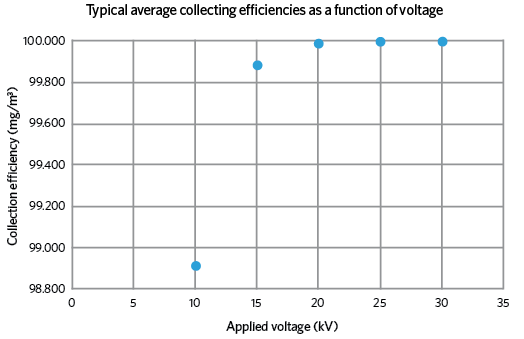
Figure 2: Variation of collection efficiency with applied voltage
A catalyst for change
There is no reason why ESPs should not become a standard part of an air handling unit if a catalyst is introduced that removes ozone. The collection efficiency of these devices across a broad range of particle sizes is high and, unlike fabric or mat-type filters, the pressure drop across them is low and remains constant, offering considerable savings in running costs.
Figure 1 is a cross-section through a new design of precipitator that is being researched and developed by the author, which addresses the perennial problem of re-entrainment. Dust particles are charged on entry by the centrally located ‘wire’ electrode; these then migrate towards the oppositely charged or grounded collecting cylinder, where they slowly build up into a cake, which is routinely removed. An additional feature of this design is the fine, stainless steel mesh cylinder, which is sealed round the exit aperture and given the same charge as the particles. This causes a repelling action that forces the particles towards the collecting cylinder, but allows the uncharged, cleaner air to pass through. This considerably increases the overall collecting efficiency of the device (see Figure 2).
Ozone degradation by adsorption using a catalyst
In catalytic decomposition, the atomic structure of a molecule can be changed without the catalyst undergoing chemical change. With ozone, this is achieved by the transient adsorption of the loosely bonded oxygen atoms in its molecules. Desorption takes place rapidly, leaving spaces on the catalyst’s surface for a continuous adsorptive/desorptive process.
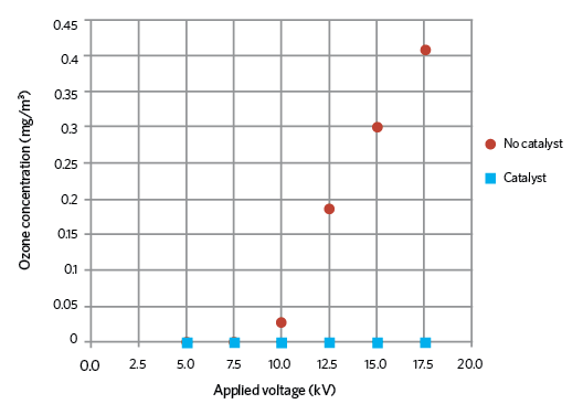
Figure 3: Ozone concentrations with and without catalyst
The catalyst material chosen during tests was fine manganese dioxide (MnO2) powder, which does not pose a threat to health and safety, or damage the environment. Figure 3 shows the rise in ozone production as the applied voltage increases with no catalyst, and that there was no detectable ozone when the catalyst was in place. From the ESPs inlet to outlet, there is negligible pressure drop when using an ozone catalyst. This remains constant because there is no interruption to the airflow.
The American ceramic ozone catalyst tested indicated a pressure drop across of 50Pa at an air velocity of 2.5m·s-1. The author has designed a catalyst that, it is hoped, will match – or improve on – this performance.
The efficiency of ESPs can be as high as any other system given the right design for each application. By incorporating a catalyst, it is possible to control ozone that is drawn into and produced by ESPs operating at ambient temperature (~20°C) and pressure (1 bar)

Tuesday, 28 May 2019

Indirect Evaporative cooling can save energy when used in the right climate. Ex Las Vegas and London Condition , why the cooling method is making a comeback


Indirect Evaporative cooling can save energy when used in the right climate

CIBSE Journal June 2017 evaporative cooling
With an increasing interest in the use of refrigerants with a low global warming potential (GWP), engineers are looking to nature’s refrigerant – R-718, better known by its chemical formula, H2O.
Evaporative cooling is not a new concept; its use in buildings can be traced back thousands of years. However, renewed interest is spurring innovation in evaporative-cooling technologies. This article will discuss some of these and their applications, with a focus on direct and indirect evaporative cooling.

Figure 1: Air handling unit with direct evaporative cooling
The effectiveness of evaporative cooling is largely dependent on the climate in which it is being considered. Hot, arid climates are the obvious choice for its use, whereas humid climates will limit its effectiveness. In favourably mild climates, evaporative-cooling technologies have the potential to replace vapour-compression cooling systems. However, for most suitable climates it will need to be supplemented with some form of mechanical cooling.
Direct evaporative cooling (DEC) – the process of adding moisture directly to an airstream and allowing the latent heat of evaporation to cool the air – is typically achieved using a wetted medium installed in an air handling unit. This method is generally preferred to spraying water into the airstream.

Figure 2: Air handling unit with indirect evaporative cooling
The process follows the constant wet-bulb line towards saturation, while the dry-bulb temperature decreases. The effectiveness of evaporative media, often referred to as the saturation efficiency, determines how close to saturation the air becomes. Saturation efficiency, defined by the equation on the left, is a function of the media depth and the air velocity through the media.
Indirect evaporative cooling (IEC) relies on a secondary airstream, in which the evaporative cooling process takes place and sensibly cools the primary airstream via a heat exchanger. The secondary airstream can be exhaust/return air from the building, or ‘scavenger’ air from outside.
The advantage of indirect over direct evaporative cooling is that no moisture is added to the primary airstream. The disadvantage is that it is less efficient at cooling because of the added heat-exchange process between the primary and secondary airstreams. Indirect evaporative cooling is more suited to building types where humidity control is required – for example, a laboratory.

Both systems (direct or indirect) or a combination of the two (indirect/direct) offer significant potential in the right climate to save cooling energy. Energy savings are achieved either by eliminating the need for mechanical cooling, or by extending the range of economiser hours – to reduce chiller operating hours – and reducing the mechanical cooling load.
Parasitic energy losses need to be accounted for when designing and optimising evaporative cooling systems. These losses take the form of additional fan power associated with pressure loss across the evaporative media. For an indirect evaporative cooling system, this includes additional fan power required at the supply and exhaust/scavenger fans.
The case for evaporative cooling has been evaluated for direct, indirect and indirect/direct technologies in three distinctly different climates – London, Las Vegas and Hong Kong . The analysis assumes an office building with a typical occupancy profile and a central variable air volume (VAV) system to condition the building. Additional fan power (parasitic losses) are accounted for in the analysis.
Ambient design conditions
Reviewing the weather data for each location is insightful in predicting how effectively evaporative cooling will perform in each climate. A psychrometric chart identifying ambient design conditions during operational hours throughout an average year (TMY-2 data) is an ideal visualisation tool. Design conditions falling within Zone 2 on the chart are ideal for evaporative cooling, with conditions in Zone 3 also suitable for supplemental cooling. Zone 4 represents conditions that sit above the dew point corresponding to the supply air temperature and render evaporative cooling ineffective.

The psychrometric weather data chart for Las Vegas (Figure 3) shows a significant number of hours suited to evaporative cooling (Zones 2 and 3). There are only a handful of hours when evaporative cooling would be ineffective (Zone 4).
Weather data for London in Figure 4 demonstrate some clear opportunities for evaporative cooling (Zones 2 and 3) with only a small proportion of hours in Zone 4.
As Figure 5 shows, Hong Kong is synonymous with a hot and humid climate. Significant hours of weather data reside in Zone 4, where evaporative cooling is ineffective. We can infer that evaporative cooling is likely to have very little effect in this climate.

The results for the energy study are summarised in the chart (Figure 6) and align with expectations. In Hong Kong, direct, indirect and indirect/direct evaporative cooling systems offer very little reduction in cooling energy. The additional fan power energy (parasitic losses) generally make evaporative cooling more energy intensive than the baseline condition.
In London, direct evaporative cooling gives a 28% saving over the baseline,
while indirect/direct evaporative cooling enables further savings in cooling energy. However, the additional fan power is detrimental to the overall performance.
Finally, Las Vegas – a desert-like climate – demonstrates substantial savings in cooling energy, with an indirect/direct evaporative solution offering as much as a 79% saving over the baseline.
There are some standard assumptions embedded in the analysis above, including the depth of wetted media (200mm) and configuration of the components within the air handling units. Both are variables that can be configured to optimise the system performance. For example, increasing the depth of the wetted media will increase the saturation efficiency and, therefore, the evaporative cooling effect. However, with increased media depth comes increased pressure drop, resulting in higher fan energy.

Figure 6: Evaporative cooling energy-saving potential by system type and location
The depth of the wetted media should be studied on a case-by-case basis to optimise for overall energy performance.
Another consideration is the location of the supply fan(s) relative to the evaporative media. A blow-through fan configuration gives sensible fan heat upstream of the evaporative media, increasing the wet-bulb depression ahead of the evaporative cooling process. This improves the performance when compared to a draw-through fan configuration, where sensible fan heat is added downstream of the evaporative media.
Additionally, the use of a bypass damper should be considered for the evaporative media. Not only does this reduce fan energy when the evaporative cooling section is inactive, but it also provides some controllability of the air temperature downstream of the evaporative media, which can be subject to over-cooling.
The water-energy nexus
On a final note, it behoves engineers to consider the water consumption for any evaporative cooling solutions. The suggestion that evaporative cooling could save water as well as energy might sound contradictory, until you look beyond the building level and consider the water-energy nexus.
In the case of Las Vegas, the state of Nevada gets most of its electricity generation from hydro-electric power – think Hoover Dam. The evaporation losses from hydro-power and, to a lesser degree, fossil-fuel power plants, are such that every kWh of energy consumed in Nevada uses 27 litres of water at the source.
So, in the case in Las Vegas, the direct evaporative cooling solution consumes an estimated 1.2 million litres/year in site water, but saves approximately 1.45 million litres/year of source water tied to a reduction in electricity consumption.
The above is an extreme case – and in many other examples of evaporative cooling there will probably be an increase in water consumption – but it draws attention to the importance of looking beyond the site metrics in any study.

Monday, 27 May 2019

Energy Efficient Technology , Energy saving , Indoor Air Quality , low space use The chilled beam

chilled beam is a type of convection HVAC system designed to heat or cool large buildings. Pipes of water are passed through a "beam" (a heat exchanger) either integrated into standard suspended ceiling systems or suspended a short distance from the ceiling of a room.As the beam chills the air around it, the air becomes denser and falls to the floor. It is replaced by warmer air moving up from below, causing a constant flow of convection and cooling the room. Heating works in much the same fashion, similar to a steam radiator. There are two types of chilled beams. Some passive types rely solely on convection, while there is a "radiant"/convective passive type that cools through a combination of radiant exchange (40%) and convection (60%). The passive approach can provide higher thermal comfort levels,while the active type (also called an "induction diffuser") uses the momentum of ventilation air entering at relatively high velocity to induce the circulation of room air through the unit (thus increasing its heating and cooling capacity).
The chilled beam is distinguishable from the chilled ceiling. The chilled ceiling uses water flowing through pipes like a chilled beam does; however, the pipes in a chilled ceiling lie behind metal ceiling plates, and the heated or cooled plates are the cause of convection and not the pipe unit itself. Chilled beams are about 85 percent more effective at convection than chilled ceilings. The chilled ceiling must cover a relatively large ceiling area because it provides heating and cooling mainly by radiant, rather than convective, heat transfer

Physics

Water can carry significantly more energy than air. Although 1 cubic foot (0.028 m3) of air has a capacity to hold heat of 37 joules per kelvin (JK−1), the same volume of water has a heat capacity of 20,050 JK−1. A metal pipe of water just 1 inch (2.5 cm) in diameter can carry as much energy as an 18-by-18-inch (46 by 46 cm) metal duct of air. This means that chilled beam HVAC systems require much less energy to provide the same heating and cooling effect as a traditional air HVAC system.
Chilled beam cooling systems require water to be treated by heating and cooling systems. Generally, water in a passive chilled beam system is cooled to about 16 to 19 °C (61 to 66 °F). In active chilled beam heating systems, water temperature is usually 40 to 50 °C (104 to 122 °F). (Chilled beam heating systems usually cannot rely solely on convection, however, and often require a fan-driven primary air circulation system to force the warmer air to the ground where most people sit and work.) There are effectiveness and cost differences between the two systems. Passive chilled beam systems can supply about 5.6 to 6.5 watts per foot (60 to 70 watts per metre) of cooling capacity. Active chilled beam systems are about twice as effective. In both cases, convection is so efficient that the ratio of incoming air to heated/cooled air can be as high as 6:1. However, studies of the energy cost-savings of active versus passive chilled beam systems remained inconclusive as of 2007, and appear to be highly dependent on the specific building.
The active chilled beam system employs fins to help heat and cool.Active chilled beam systems are effective to the point where outdoor air can be mixed with the indoor air without any traditional air conditioning (such as heating, cooling, humidifying, or dehumidifying), thus enabling a building to meet its "minimum outdoor air" air quality requirement.

Advantages and disadvantages

The primary advantage of the chilled beam system is its lower operating cost. For example, because the temperature of cooled water is higher than the temperature of cooled air, but it delivers the same cooling ability, the costs of the cooled water system are lower. Because cooling and heating of air are no longer linked to the delivery of air, buildings also save money by being able to run fewer air circulation fans and at lower speeds. One estimate places the amount of air handled at 25 to 50 percent less using chilled beam systems. By being able to target the delivery of clean outdoor air where it is needed (rather than injecting it into the entire system and heating or cooling it), there is a reduced need to treat large amounts of outdoor air (also saving money). In one case, the Genomic Science Building at the University of North Carolina at Chapel Hill lowered its HVAC costs by 20 percent with an active chilled beam system. This is a typical energy cost savings. Chilled beam systems also have some advantages in that they are almost noiseless, require little maintenance, and are highly efficient.Traditional fan-driven HVAC systems create somewhat higher air velocities, which some people find uncomfortable. Chilled beam HVAC systems also require less ceiling space than forced-air HVAC systems, which can lead to lower building heights and higher ceilings. Since they do not require high forced air flows, chilled beam systems also require reduced air distribution duct networks (which also helps to lower cost).
Chilled beam systems are not a panacea. Additional ductwork may be needed to meet minimum outdoor air requirements. Both types of chilled beam systems are less effective at heating than cooling, and supplementary heating systems are often needed. Chilled beam systems cannot be used alone in buildings where the ceilings are higher than 2.7 metres (8.9 ft), because the air will not properly circulate. A forced-air circulation system must be employed in such cases. If the water temperature is too low or humidity is high, condensation on the beam can occur—leading to a problem known as "internal rain." (In some cases, drier outside air can be mixed with the wetter inside air to reduce interior humidity levels while maintaining system performance.) Chilled beam systems are not recommended for areas with high humidity (such as theaters, gymnasiums, or cafeterias). Because they are less effective at cooling, passive chilled beam systems are generally ill-suited for semi-tropical and tropical climates. Hospitals generally cannot use chilled beam systems because of restrictions on using recirculated air. Chilled beam systems are also known to cause noticeable air circulation which can make some people uncomfortable. (Passive air deflection devices can help disrupt these air patterns, alleviating the problem.) Some designers have found that enlarging the ducts around active chilled beam systems to increase air circulation causes echoes in working areas and amplifies the sound of water moving through the pipes to noticeable levels.

Sunday, 26 May 2019

Market Scenario of HVAC in india

India HVAC market is expected to cross $7 Billion by 2022. Growing infrastructure-based developments, technological advancements and increasing tourism are expected to positively influence India HVAC market over the next five years. Moreover, extreme climatic conditions, rising disposable income, growing construction activities in both commercial and residential sectors coupled with various government initiatives aimed at improving energy efficiency are some of the other major factors expected to boost India HVAC market during the forecast period.
Years considered for this report:
Historical Years: 2012 – 2016
Base Year: 2016
Estimated Year: 2017
Forecast Period: 2017 – 2022
Objective of the Study:
  • To analyze and forecast market size of India HVAC market, in terms of value as well as volume
  • To define, classify and forecast India HVAC market on the basis of product type, by end use sector, and by region
  • To identify tailwinds and headwinds for India HVAC market
  • To examine competitive developments such as expansions, new product launches, supply contracts, and mergers & acquisitions in India HVAC market
  • To evaluate competitor pricing, average market selling prices and trends in the India HVAC market
  • To strategically profile the leading players, which are involved in the supply of HVAC systems in India

Some of the major players operating in India HVAC market are Voltas Limited, Daikin Air Conditioning India Pvt. Ltd., LG Electronics India Pvt. Ltd., Johnson Controls-Hitachi Air Conditioning India Limited, Honeywell Automation India LTD., Thermax Limited, Blue Star Ltd., Samsung India Electronics Pvt. Ltd., Carrier Airconditioning & Refrigeration LimitedETA Engineering Pvt. Ltd, Panasonic India Pvt. Ltd., etc.
TechSci Research performed primary as well as exhaustive secondary research for this study. Initially, TechSci Research sourced a list of HVAC manufacturers and suppliers in India. Subsequently, TechSci Research conducted primary research surveys with the identified companies. While interviewing, the respondents were also enquired about their competitors. Through this technique, TechSci Research was able to include manufacturers that could not be identified due to the limitations of secondary research.
TechSci Research calculated the market size for India HVAC market using a bottom-up approach, where manufacturers’ value and volume sales data for different types (direct expansion systems and central air conditioning systems) HVAC was recorded as well as forecast for the future years was done. TechSci Research sourced these values from industry experts and company representatives, and externally validated through analyzing historical sales data of respective manufacturers to arrive at the overall market size. Various secondary sources such as company annual reports, white papers, investor presentations and financial reports were also used by TechSci Research.

Key Target Audience:
  • India HVAC Manufacturers
  • India HVAC Suppliers 
  • Research Organizations and Consulting Companies
  • Associations, organizations, associations and alliances related to HVAC
  • Government bodies such as regulating authorities and policy makers
  • Industry associations
  • Market research and consulting firms
The study is useful in providing answers to several critical questions that are important for industry stakeholders, such as HVAC manufacturers, distributors, dealers and policy makers. The report would also help the stakeholders in identifying which market segments should be targeted over the coming years (next five years) in order to strategize investments and capitalize on the emerging market opportunities.